by Mark Brazelton
Ever since my original gas pedal wore out and I switched to an aluminum racing pedal, I've been struggling to obtain the smooth pedal operation I was after. Recently I noticed a few members had installed the 1971-72 C10 cable throttle in their 60-66 trucks. Further research showed this to be a very popular swap with the 67-70 crowd as well.
Other than two photographs another member posted, there wasn't much helpful information available. When I finally decided to install the cable throttle in my 1960 GMC I took a few pictures that may prove helpful to others wanting to do the same swap.
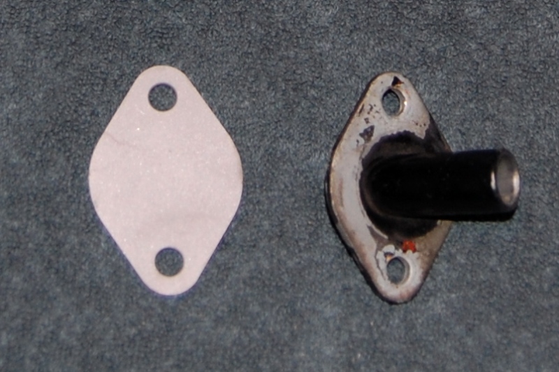
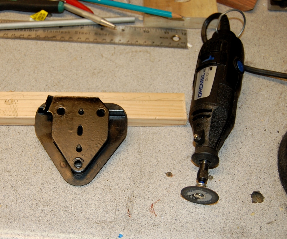
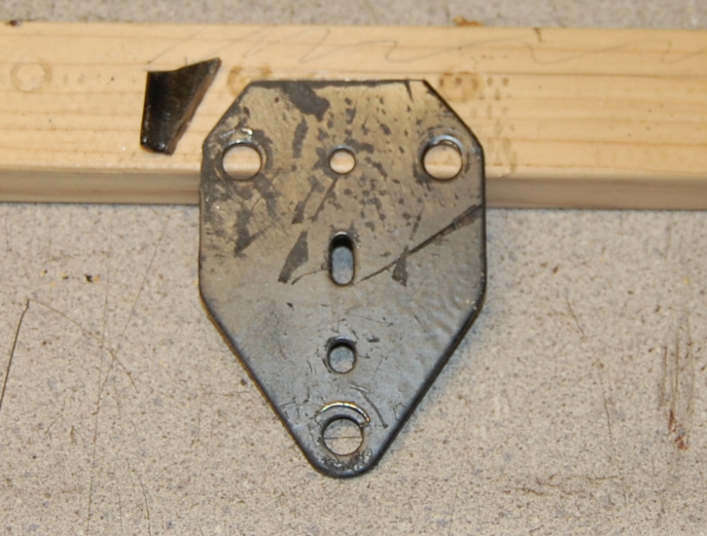
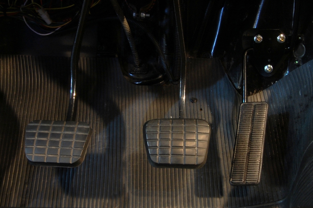
First up I removed the pedal, firewall pivot, and all the linkage up to the carburetor. The nutserts in the floor were plugged with silicone sealant followed by a pair of 1/4x20 button head Allen screws. Using the bell crank pivot mount as a template, a block off plate (the same thickness as the pivot plate) was fabricated to cover the pivot hole.
(Click on photos to enlarge)
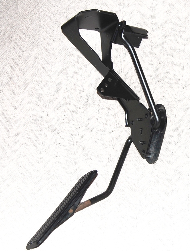

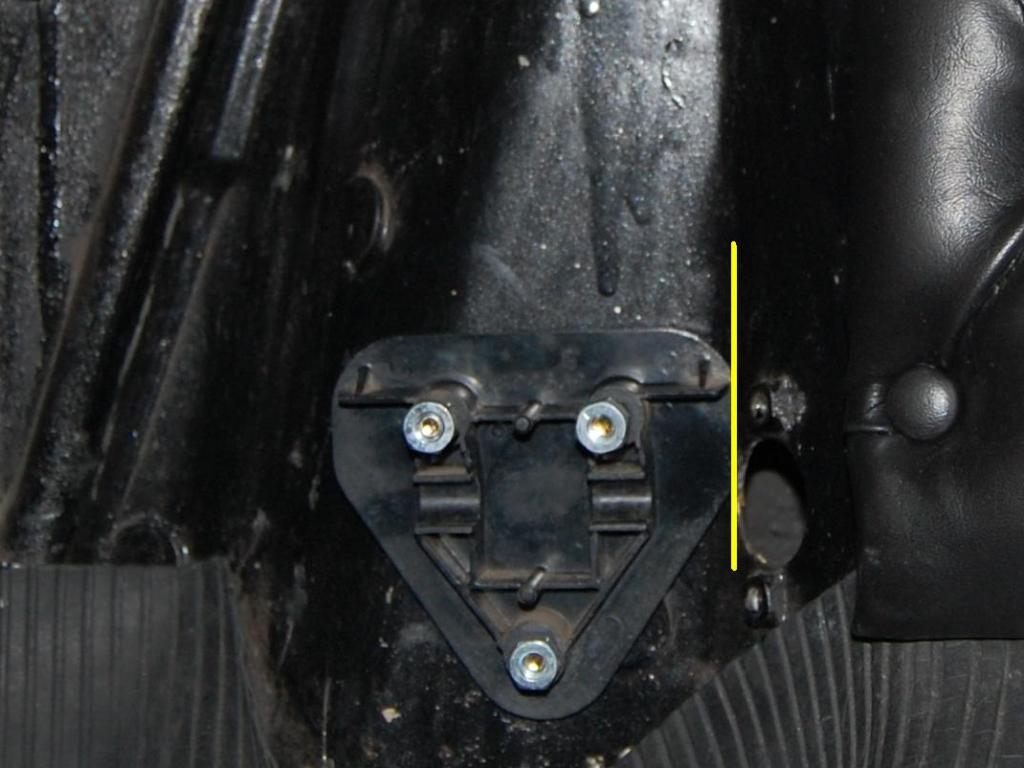
The complete assembly was test fit numerous times looking for the best fit at the firewall, the most comfortable pedal position, and level alignment. (Some of the pictures appear to lean to the left, but that's because I didn't have the camera level on the seat). Once the location was established, the upper right hole was marked with a 17/64 transfer punch (the next size up from ¼). It was a tight slip fit to keep alignment accurate. That hole alone was drilled to ¼, and the complete pedal assembly reattached to the firewall. The allowed a precise final alignment before marking the other two mounting holes.
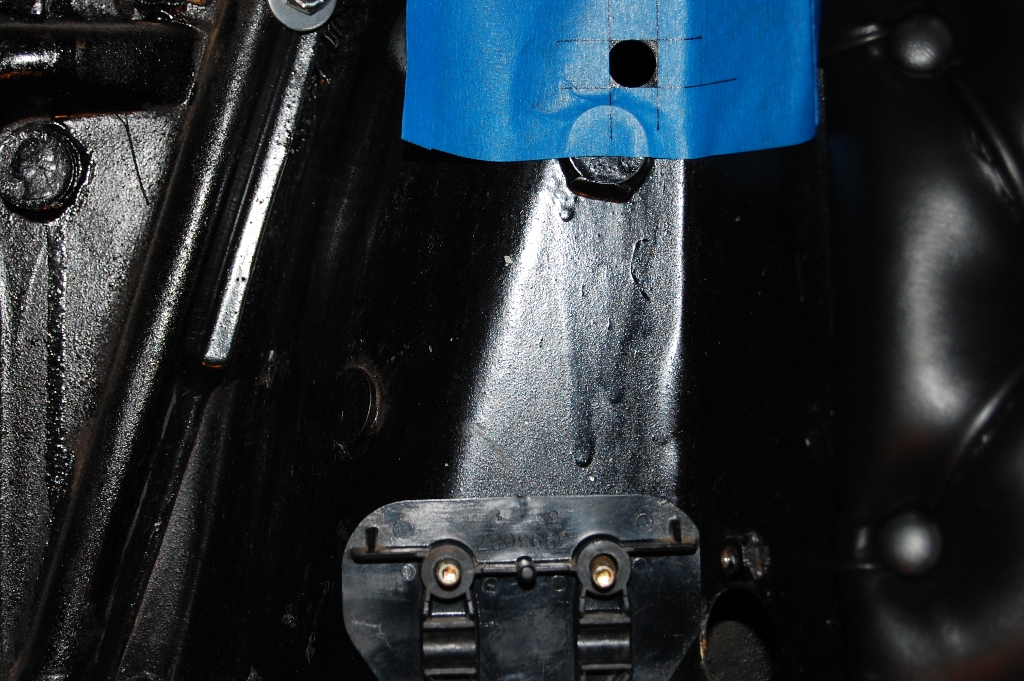
With the pedal where it belonged, the top of the bell crank needed to move about ½ to the left. It was clamped in the bench vise at the point indicated by the arrow, and given a gentle nudge with an 18 adjustable wrench. Bolted back in place, the upper cable hole was marked with a 5/32 transfer punch directly through the cable restraint bushing.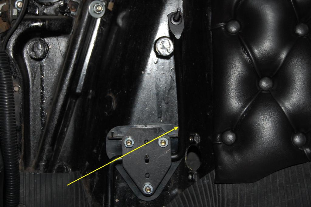
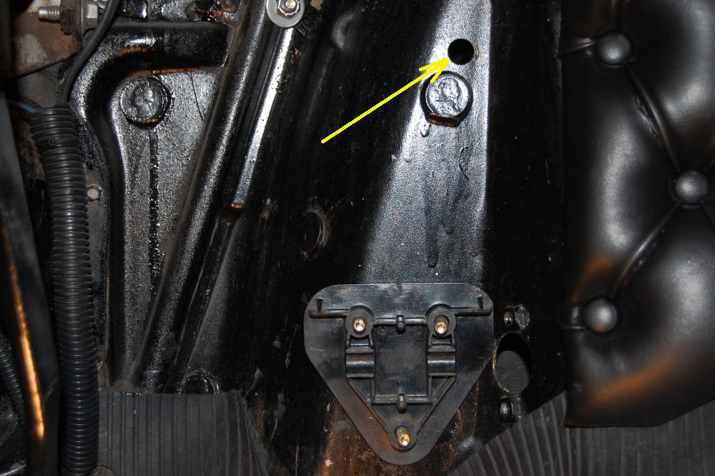
And finally the cable hole was drilled out to ½.
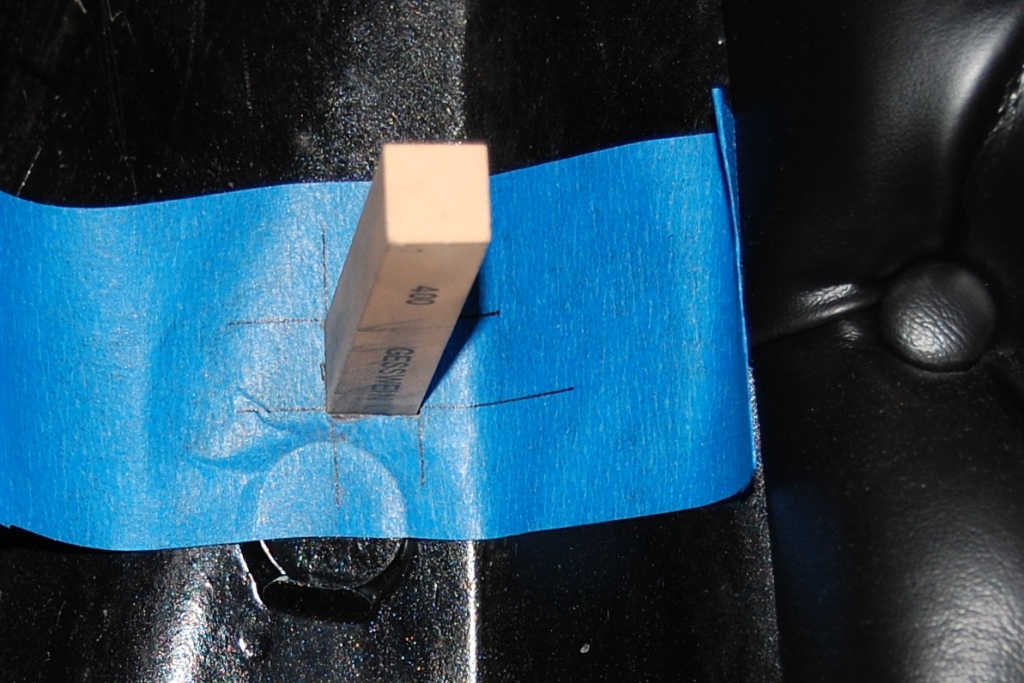
To help insure the cable hole came out square and level, I started out by making a template/guide. I applied a length of 2 masking tape to one of my wife's cutting boards. A ½ square was marked and cut out freehand with an Xacto knife.
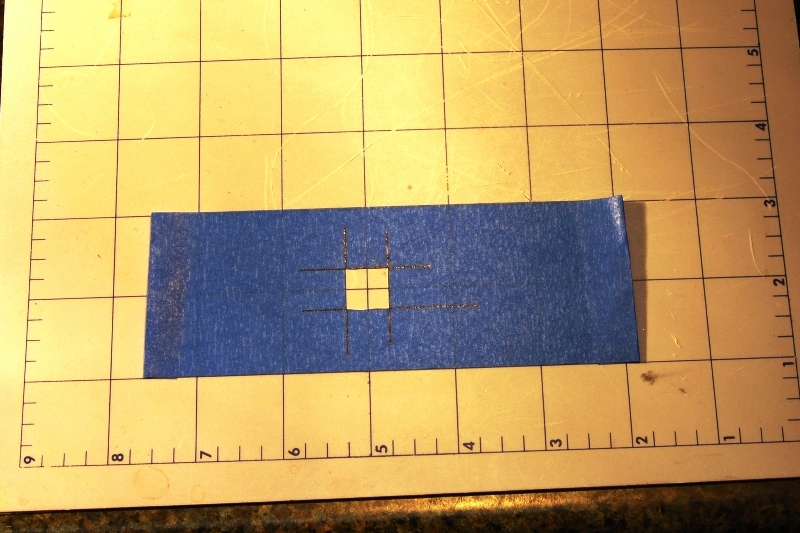
There was less to remove than I expected, and the corners were quickly squared up with a small triangle file. It occurred to me I have a 400 grit stone in my stash, so I checked and sure enough it is exactly ½ square. So I used it for a go/no go gauge until it slipped through. Now I have a nice 400 grit polish on the edges of the opening.
After vacuuming up the last of the mess the cable was slipped in place and the pedal assembly installed. The cable remained loose until the carb connections were complete to allow for best routing.
Engine Connections:
A ball stud was added to the side of the Edelbrock carburetor linkage as I had previously been using the large hole in the forward position.
I didn't have a bracket available to mount the forward end of the throttle cable. I looked through everything Edelbrock had to offer and didn't find anything that looked suitable. A couple more hours of internet searching turned up this Holley/GM bracket. Holley part number 20-44.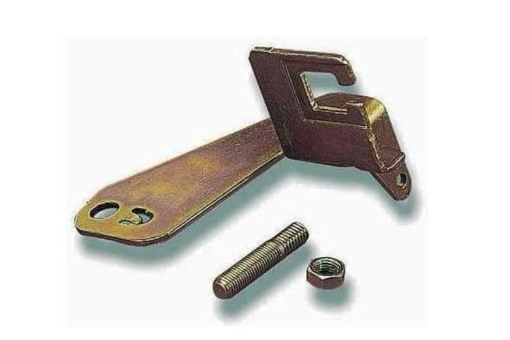
This turned out to not be the best available choice because it needed modification to fit my particular installation.
Subsequently I discovered Holley part number 20-88 which would have bolted to the outboard stud on my Edelbrock carb and saved me at least 2 hours of wasted time.
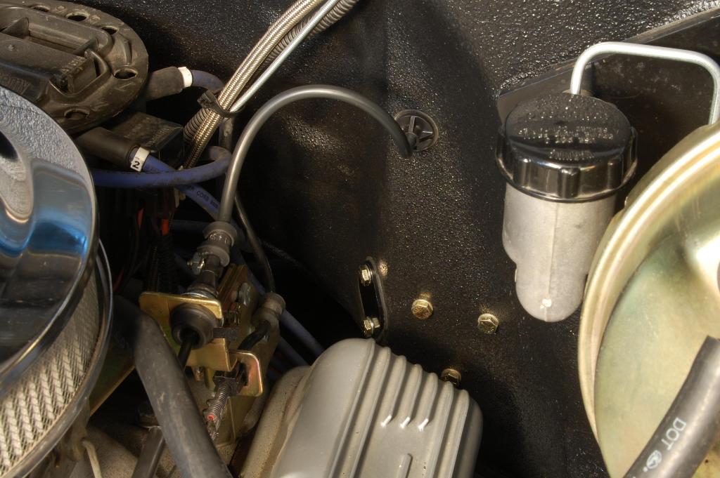
Here's what the engine side looks like all back together. This one shows the mounting bolts for the gas pedal support, the cable attachment, and the block off plate for the old linkage pivot.
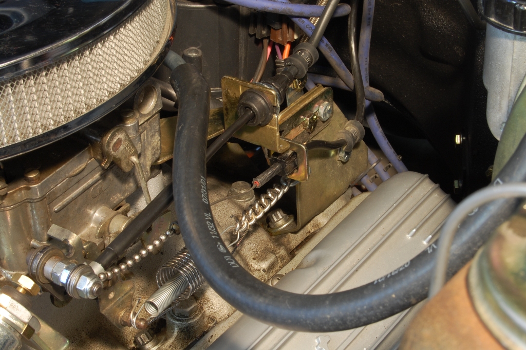
And this is the best shot I can get of the engine brackets. The new bracket moved the anchor for the throttle return springs back almost an inch and a half stretching them too tight. So I added a high tech adjustable return spring connector (a piece of dog chain). Once I dial in the correct length, I'll have my kid whip up something a little fancier looking. (Obviously I need to wash my engine again!)
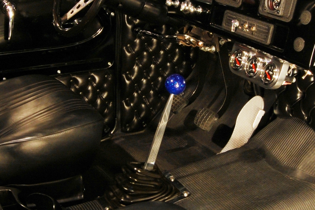
The interior changes from start to finish took longer to write up and take pictures of than it did to perform the actual modifications. Compressed into actual working time it probably took less than a couple of hours to do the whole conversion.
Final notes - the standard 1972 350 cable is actually several inches too long for my application requiring a pretty severe corkscrew routing between the firewall and the carburetor. Apparently my engine is closer to the firewall than a stock 71-72 C10. The 4x4 version is shorter, but I don't know by how much. It might have been a more suitable choice, but OEM versions are claimed to no longer be available.
In order to keep the cable level with the throttle linkage I added an Adel clamp to the kick down bracket which also removed any strain from the factory cable/bracket attaching grommet.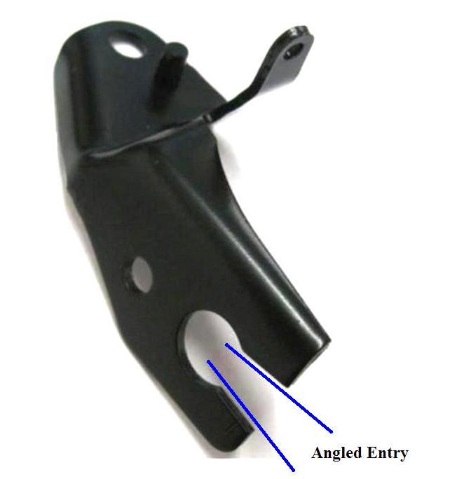
After the first test drive with the new cable setup I knew this upgrade was a smart investment. What an unbelievable difference. I would have made the change years ago had I known how much of an improvement it was going to make. It is smooth as glass and extremely precise. The final minor adjustment was increasing throttle spring tension by one notch. The cruise control worked perfectly requiring no adjustment at all. Having been a mechanical linkage guy for the last 45 years I'm surprised how delighted I am with the results of this conversion. I'll be recommending cable gas pedals from now on.